|
[?]Subscribe To This Site
|
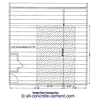
Steel Beam DesignThe steel beam design for I beam described in steel beam sizing is the exact same procedure for designing any structural steel tube beam, steel c channel beam or structural steel angles. For the sake of the illustrating the design of steel beam, let’s consider the beam shown below, assuming suspended slab for garage - all dimensions are the same.
For a concrete suspended slab over metal deck, the dead load will be much higher. Here are the assumptions: 1. Total slab thickness 7.5 inches – 7.5/12*150 pcf = 93.75 psf 2. 20 gage 2 inch deck – 3.59 psf 3. Ceiling – 3.3 psfDead Load = 100.64 psf. Live Load = 40 psf Total load = 100.64psf + 40psf = 140.64 psf. The formula for determining the moment is M = wL^2/8 where w is the load in pounds per foot or kilopounds (kips)per foot, L is the clear span length of the beam being designed. Please note the unit for w and L must be the same i.e. if w is expressed in pounds Multiplying the total load by the tributary width of 12’-7”, 140.64x12.58 all divided by 1000 to convert to kips equal 1.77 klf (kips per lineal foot). Substituting to M = wL^2/8 = 1.77x19^2/8 = 79.87 kip-ft or 958.44 kip-in. The section modulus required is S = M/.66Fy = 958.44/33 = 29 cubic inches which is less than Sx = 33.4 for a W12x26 so the selected beam is ok for suspended slab garage floor. To see wide flange or i beam dimensions and sizes as well as section modulus click here. Please note the section modulus are listed under Sx column. Sy is also section modulus but in the weak axis if the beam is to be installed sideways, something that should never happen. Back to to the top |
|


