|
[?]Subscribe To This Site
|
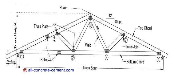
Residential Roof Truss DesignThis page is a continuation of calculation of the residential roof truss design as described in this page which is the first step for making roof trusses. The intend of this page is to provide information as to how to build roof trusses, especially if prefabricated roof trusses are not available. Since roof truss construction requires a lot of tedious calculations and very labor intensive, the aim of provide these calculation is to demonstrate that point. Once the dead load and live loads are determined, it is time to apply those loads in to the joints of the trusses. The reason for numbering the joints as shown in the diagram below was to aide with the calculations. Even though the truss members were not numbered, it is a good idea to label them to make the analysis and building roof trusses easier.One of the challenges of analyzing trusses is figuring the angles that each truss member makes relative to each other or relative to the vertical and horizontal axes. This requires a lot of trigonometry, geometry, as well as algebra.
To transfer the 27.1 psf total load to the truss joints, we need to multiply the total load by the truss spacing of 2 ft center to center. This yields 54.2 plf. Using the horizontal distances between joints and using the tributary area method one half the loads in between joints will be applied to the joints, the loads will be evenly distributed throughout the truss configuration.
Going from left to right in the diagram above, the horizontal dimensions are 4.75ft from joint 1 to 5, 2ft from joint 5 to 2, 2ft from joint 2 to 6, 2ft from 6 to 3, 2ft from 3 to 7, 4.75ft from joint 7 to 4. The total load at joint 1 will be 54.2x4.75/2 = 64.4 pounds. At Joint 5 the horizontal length is 54.2 x (9 4.75/2 + 2/2) = 91.5 pounds Back to residential roof truss design From residential roof truss design to all-concrete-cement.com |
|


