|
[?]Subscribe To This Site
|
Metal Roof TrussesContinuing the metal roof trusses discussion from steel roof truss design which outlines the beginning stage of roof truss engineering that can be used for steel roof truss. Analyzing the truss joints in order to determine the member forces is one of the procedures for making roof trusses. This type of analysis for building roof trusses can be very tedious because it involves a lot of trigonometry and arithmetic that can easily lead to errors. The assumption used previously is the truss was to be built with steel angles L3x3x1/4 but it can be any type of steel. Steel channels or tube steel can be use or round pipes. There are a lot of steel trusses designed for aesthetic reasons use round pipes, square or rectangular steel sections. Some design use combinations of wideflange, circular and rectangular steel sections.The longest steel truss I had worked on was 260 feet clear span for a Convention Center in Las Vegas. The bottom chords were W14x426 turn sideways with W12x230 as top chords, truss depth was 20ft with W10x100 as web members. The trusses were so massive that it required two cranes side by side to lift one truss into position, held in place in order for welding to take place. Each truss sat on built-up columns that made of 4 inch thick plates for flanges and web.
The common truss top and bottom chords members are WTs (I beams cut it half) with steel channels or angles used as web members. For exposed to view trusses, square tubes for top and bottom chords and round pipes as web member are the norm but these are all depends on designers/architect choice.
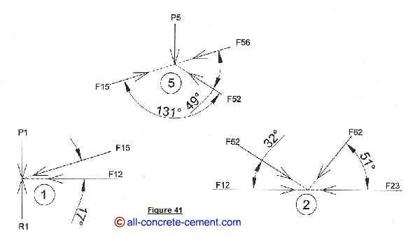
To analyze the forces at joint 1, let’s calculate the reaction forces R1 and R2. The total load 144.8 plf multiply by the clear span 17’-10” and then divided by 2 give us the R1=R2=1290.9 pounds The applied force P1 is 144.8x4.75/2=343.9 pounds Y Direction Forces: R1-P1-F15sine(17) = 0, F15 = 3239 pounds X Direction forces: -F12-F15cosine(17) = 0, F12 = -3097.5 pounds Back to metal roof trusses |
|


